PWM fan controller with Arduino.
Table of contents
Background
I am not an electronics guy, in fact if I avoid touching hardware when I can. Any time I can, I virtualize a machine’s tasks. The slow boot times, the anchor to a particular hardware configuration, the fickle nature of hardware… it all annoys me. To me, electronics is even grittier than that.
My point is, before this project my electronics knowledge was very limited. I had a basic understanding of how electricity works, which mostly rooted from taking apart a live space heater at a young age and electrocuting the shit out myself before the breaker popped. Before this project I had a soldering iron, heat shrink, and miscellaneous resistors from a previous project involving hot-wiring my track motorcycle for keyless start. But I had always considered the Arduino a novelty tools for electrical engineers to learn with. Not something I would ever use, much less purchase. Seems I was wrong.
What triggered this project?
Having a home build SAN has been a great addition to my homelab. It allows me to have a ton of storage in one central place and is really conductive to running a virtualized platforms. I recently upgraded my DAS chassis from a 12x 3.5″ bay unit to a 45x 3.5″ bay unit (Supermicro SC847E16-RJBOD1). This new unit was extremely loud, 53.5db according to the datasheet for the Nidec V80E12BHA5-57 fans and there are 7x fans. The fans can move some serious air (72.5 CFM), each is 80mm x 80mm x 38mm, the depth is nearly half the width/height. Fortunately, the fans do have a PWM pin (4 pin). Unfortunately this DAS does not have the hardware to make use of that pin. I speculate that Supermicro re-used many of the same components for their server platforms which would be able to utilize the 4th pin on the fan connector.
DIY
I realized that I had to build my own controller. So my journey was to find a way to control the fan speed so that the DAS would be able to operate in the house without wearing ear protection. It seriously is that loud at full tilt.
I started searching for PWM fan controllers (later on why PWM). I looked for a few days and most did not fit the bill, most were not easily going to fit in a server chassis as they were designed for a spare 5 1/4″ drive bay of which the chassis did not have and most could only control one PWM fan. Then I found the Zalman Fan MATE and was really excited. It was simple, I could hang it out one of the bays, and it was adjustable.
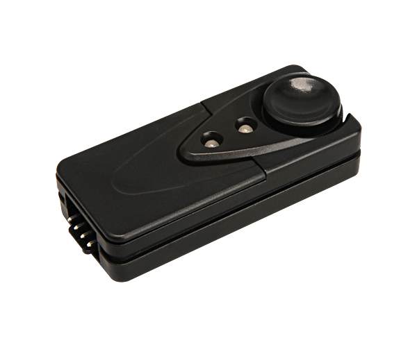
My plan was to buy the Zalman and one of these splitters to control the fans. This seem to be the answer for me BUT I could not seem to find a retailer that had the Zalman in stock or even available to place on backorder. I placed an order with one retailer, only to have them contact me a week later and say they are unable to fill my order.
Then I ran across this YouTube video and it inspired me to just build my own fan controller.
Why did I selected PWM fan control?
There are 3 practical ways to reduced a fan’s specified speed. All methods involve reducing the voltage the fan motors receives. Below are brief descriptions of how each method achieves reducing the power to the fan.
-
Inline resistors and potentiometers. This is the method that I see the most frequent and the most dangerous. The way this works is it reduces the voltage to the fans by converting the difference in voltage to heat. So if you want to run a 12 volt fan at half it’s speed, half of the energy is converted to heat. Call me crazy but it seems counter productive to create heat with a device intended to disperse heat. The dangerous part is there is potential to have the wires/resistors melt and/or catch fire. This is less of a problem when the reduction in voltage is lesser, as an example 11 volts from 12 volts. However I needed a huge reduction in fan speed to get them to acceptable noise levels. Potentiometers, are similar to inline resistors in that it dissipates the difference in voltage as heat but in a variable way with a control knob. So resistance based reduction is not an option, the potential of a house fire due to a DIY project is unacceptable.
-
Use the 5 volt rail instead. One thing you can do is instead of using the 12 volt rail to power the fans, is to use the 5 volt rail. This seriously reduces the fan speed and without generating additional heat as a by-product. However, I wanted a variable fan speed control.
-
Pulse width modulation or PWM. Up until this point, each method is static. By that I mean, time is not a component of the speed control. Each method above always has the same amount of energy being supplied. With the methods above, a constant voltage is applied to the motor over every second. However with PWM, the voltage can be pulsed so quickly that the fan effectively ‘sees’ a lower voltage than what the rail is supplying. This is with the help of clever electronics built into all PWM capable fans (4 pin fans).
A generalized example of pulse width modulation
At a 50% fan signal the fan electronics would, over a period of one second, sends 12 volts for .5 seconds and 0 volts the other .5 seconds; the motor effectively sees 6 volts being applied due to the smoothing by the fan’s internal PWM electronics. At a 75% load signal, the fan electronics (effectively a relay with signal smoothing) would send 12 volts for .75 seconds and off for .25 seconds; effective the fan sees 9 volts being applied.
The way this more specifically works is the electronics built-in to the fan listens on the 4th pin for a voltage. This voltage ranges from 5 volts to 0 volts, for the Arduino this voltage is mapped to a range 255 to 0 respectively. When 255 is applied to the fourth (signal) pin, the fan electronics knows to apply a 100% load of voltage via pins 1 and 2 (supplied 12 volts and ground). At a 50% load signal (127), the fan electronics would modulate the voltage from 12 volts to 0 volts several hundred times a second via pins 1 and 2 so that the fan motor would effectively see 6 volts being applied. Pretty neat right? PWM is the engineer’s way to control fan speed, it gives granular control without heat generation as a by-product.
Enter the Arduino
As mentioned above, I ran across a video by Sky aka catalystoftechnology on YouTube. In that video, he showed a PWM fan controller he built using an Arduino. He was kind enough to provide a basic diagram and the code he used for the project. Without this information my project would have never come to be. I did a lot of research including a trip down the local hacker space, Quelabs. After a week of adding and removing items in both an Adafruit (I highly recommend them, no affiliations) and a DigiKey shopping cart I ordered the parts needed.
Goals for fan controller
I wanted to achieve quiet a few things with this controller, when I started the project I was not sure what was possible and what was not. I figured I would prune down the stuff that was not technically possible or cumbersome. To paraphrase Bryan Cantrill, ~’everything is technically possible, it’s whether the programmer wants to do it.’
- Variable fan control
- Based on user set mode (Silent, Normal, High Load, Full Tilt)
- Adaptive speed based temperature from those speeds
- Temperature sensors
- Push button for mode selection
- LEDs
- Indicate user mode selected
- Indicate if fans have adjusted above user mode selected
- Indicate the fan controller is running
- Audible warning if fan is not spinning based on monitoring pin 3 on the fans
Programming
Before this project, the extent of my programming was elaborate bash scripts including one to parse data for Excel reports and various PowerShell scripts to increase my laziness effectiveness at work. While I was waiting for my parts to arrive, I watched many videos on Arduino projects especially ones that went over the coding. After I had a better idea of how to break stuff, I installed the Arduino software and started programming using various snippet I found.
By the time the parts were delivered, I had enough code to upload and test.
Here is the code I used on the Arduino.
Assembling
I spent about a week playing with a prototype board before starting over and creating version 2 for a better layout. At the time of this writing, I am still running on version 2 of the hardware but have plans to create a version 3.
The executed product
This is still a work in progress but I plan to upload the code and the board layouts to Github.
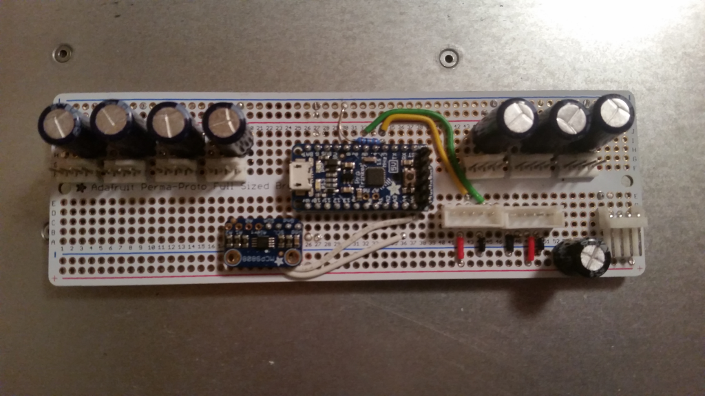
Layout as installed. Hardware version 2.
The everything is powered via a floppy disk power connector [bottom right], this breaks out the 5 volts for the Arduino (Trinket Pro), sensors, and LEDs [bottom rail]. The 12 volt rail powers the fans [top rail]. I added 1000μF capacitors for each fan to reduce the voltage dip when the fan speeds increase as they can consume 0.6 amps each. There is another 1000μF capacitor on the 5 volt rail. The two 5 pin female receptacles are for the LED and push button.
Currently there is one I²C temperature sensor mounted on the perma-proto board. In it’s current configuration there is room for 3 more sensors. When the temperature exceeds 80.0°F, the Arduino increases the speed above the current user set fan mode. After 2 minutes the condition is reevaluated and either fan speeds are decreased if below the threshold or increased if still above the threshold. This condition is reevaluated every two minutes, it is possible for the fans to spin all the way up to full tilt if the temperatures has not dropped below 80°F. The minimum fan speed is set by the user set mode. Counters are used instead of delays so the code keeps running.
I used one of the hard drive mounting sleds to house the push button and the two RGB LED panels. I used 5 pin connectors to be able to snake the wires through the backplane if I decide to move the location.

LEDs and Push buttons (Dark)
The push button increments the mode 1-4 and loops back to 1 if pressed while in mode 4. As shown in mode two [bottom right LEDs]. Push button LED on [large LED, far right].

LED and pushbutton.
The top LED panel strobes left to right and back, similar to the lights on KITT from Knight Rider. When the LEDs are white the fan speed is not being changed, when blue the fan speeds are decreasing based on temperature, and when red the fan speeds are increasing based on temperature.
The bottom LED panel indicates the mode in white LEDs and then uses the remaining LEDs to indicate (in RED) if the fans speeds are above that which is set by the user mode.
I am very happy with the end results. The fans are very quiet and the fans adaptively adjust up if the temperatures get above 80°F. Unfortunately the 1400 watt PSU has it’s own ~30mm fans and they are loud once the PSU gets hot. I will be adding a temperature sensor for the PSU, with a lower threshold to keep the PSU cooler than the rest of the system.
Here are some additional photos:
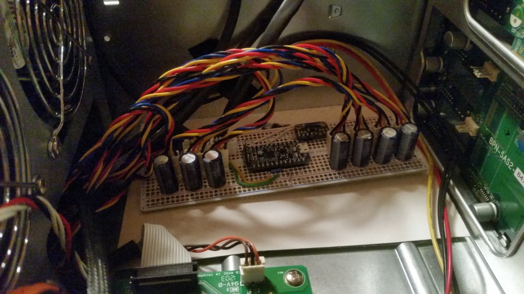
As installed in Supermicro case.
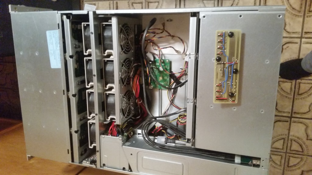
Chassis overview, not installed. Bottom side of board showing with black rubber feet.
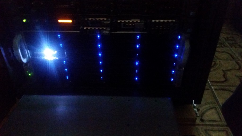
Chassis overview, powered on and in low lighting.